
7.1 Introduction
Entity Relationship model is just one of the tools and one of the oldest tools also. There are many others tools which serve slightly a different purpose but are related in the database design in one way or the other. While some of the tools are traditional like DFDs there others are modern coming from the IBM Unified Process (used to be Rational Unified Process)
In this chapter we give an overview of such tools
Data Flow Diagrams DFD
Data Flow Diagrams or DFDs for short are a behavioral model. They fall in the same category as state chart diagrams which is also a behavioral model. DFDs may be used to model the system’s data processing. These show the processing steps as data flows through a system. It helps to answer questions like where is this particular piece of information generated? Where is it getting modified?
DFDs are an intrinsic part of many analysis methods. It uses simple and intuitive notation that customers can understand. It show end-to-end processing of data.
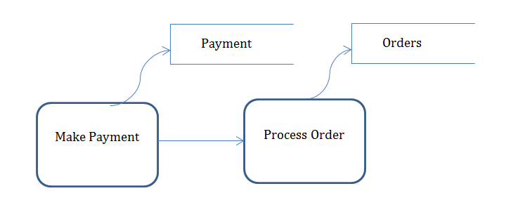
The symbols used by the DFDs are :
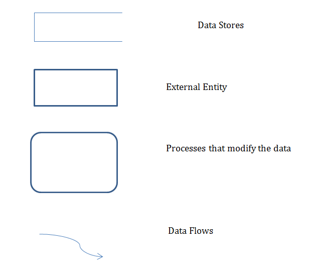
Here is brief example:
Use Cases
Use cases are a way of describing the systems requirements. It uses a diagrammatic notation as well as a narrative notation. It works with Actor, Scenario and Extension. Here is an example:
UC2: Lend Book
Primary Actor: Librarian
Pre-condition:
Trigger: A member brings a book
Main Success Scenario:
1. Scan the book
2. System shows the details
3. Enter member details
4. Print return date on book
5. Release the book
Extensions
2.a. Book is not registered
2.a.1 register the book
3.a member is not registered
3.a.1 register the member
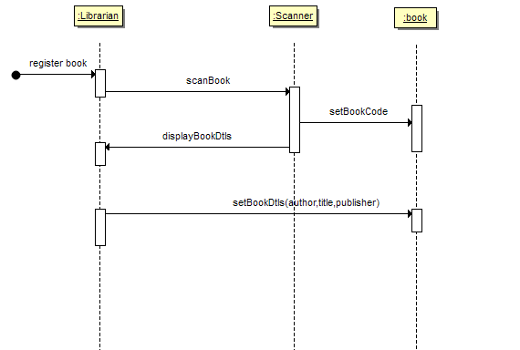
System Sequence Diagram
System Sequence diagrams or SSDs are another unified process artifact. It shows what happens in a system sequentially.
Class Diagrams
Is again another Unified process tool. Mostly used to depict Object Oriented Classes some of the information can be used to design Tables as well – as it shows the attributes that are there in a class. However none of the above diagrams are a replacement for a ER diagram.
